Tag Archives: servos

weekend project: minimalistic servo arm

There’s a video of it in its final state, with its multitude of issues. *sigh* one day I will actually finish a project. Only the first and last 5 seconds or so are interesting. Cost: ~$6 for the two microservos (!! so cheap), plastic is free, then the board+microcontroller battery is $25+$15+free (probably $10?).

After building hexa-rideablepod, I have definitely been more inclined to daydream about small or fold-able or compact project.

I should update my project todo list.

Anyway,
I started at ~8pm on Saturday and finished ~3:30 pm on Sunday (and yes, I did sleep a bit, as well as watch an anime movie (Summer Wars) …


what the cloud looks like in the future

… and spend a lot of time reading about inverse kinematics and poking at IK code I never ended up using).

I was inspired by http://www.instructables.com/id/Robotic-Arm-with-Servo-Motors/?ALLSTEPS

The code looks pretty straightforward.

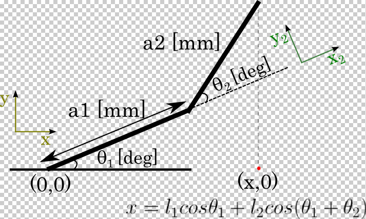
// Given theta1, theta2 solve for target(Px, Py) (forward kinematics)
void get_xy() {
  actualX = a1*cos(radians(theta1)) + a2*cos(radians(theta1+theta2));
  actualY = a1*sin(radians(theta1)) + a2*sin(radians(theta1+theta2));
}

I was a bit confused by the definitions of the variables, since I haven’t done kinematics in a while. In the forward kinematics part it is essentially saying:

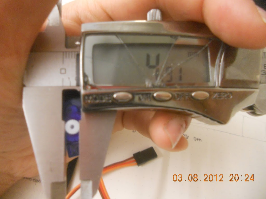
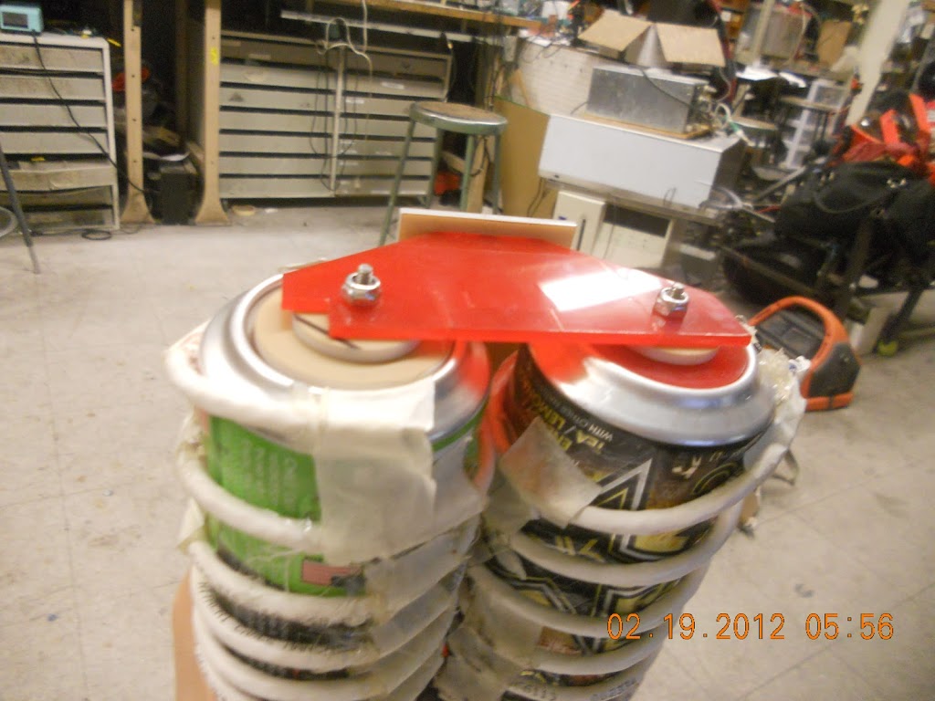
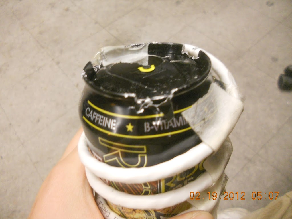
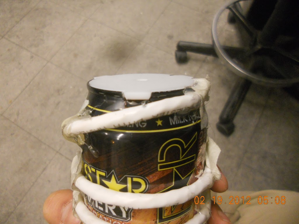
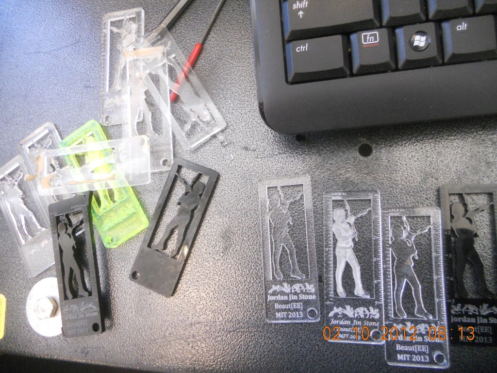
measuring the servo spline outer diameter in order to create lasercut female splines on my parts instead of using the proprietary servo horns. I started around this time. I swear I spent like 30 minutes trying to figure out how many divots it has (21) before just trial-erroring it, lol.

It gets to be pretty late in the day after I try to struggle to remember kinematics.
Here are some beautifully written kinematics notes I found linked from stackexchange question on drawing robots (robotics stackexchange! i’m excited).

Well, crap. I hesitate — do I want to try to get something done and present a project or not? I eventually decide (and with some support from the awesome Jessica Artiles) that I may as well get more feedback on my ideas. What is there to lose?

Thus, I emergency hot-glued some potentiometers onto pieces of plastic and used that as my control ( a simple mapping of potentiometer values to servo values is all that’s needed) instead of writing IK code. This arm controller design was inspired by http://www.maxjusticz.com/a-miniature-robotic-arm-controller/.

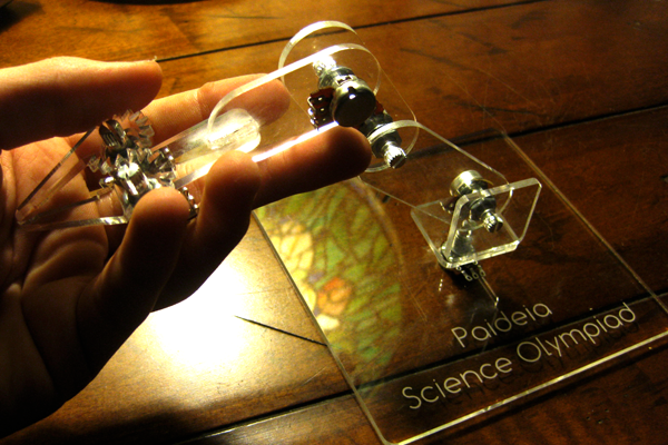
img src my design inspiration, except mine was jankier and used more hot glue

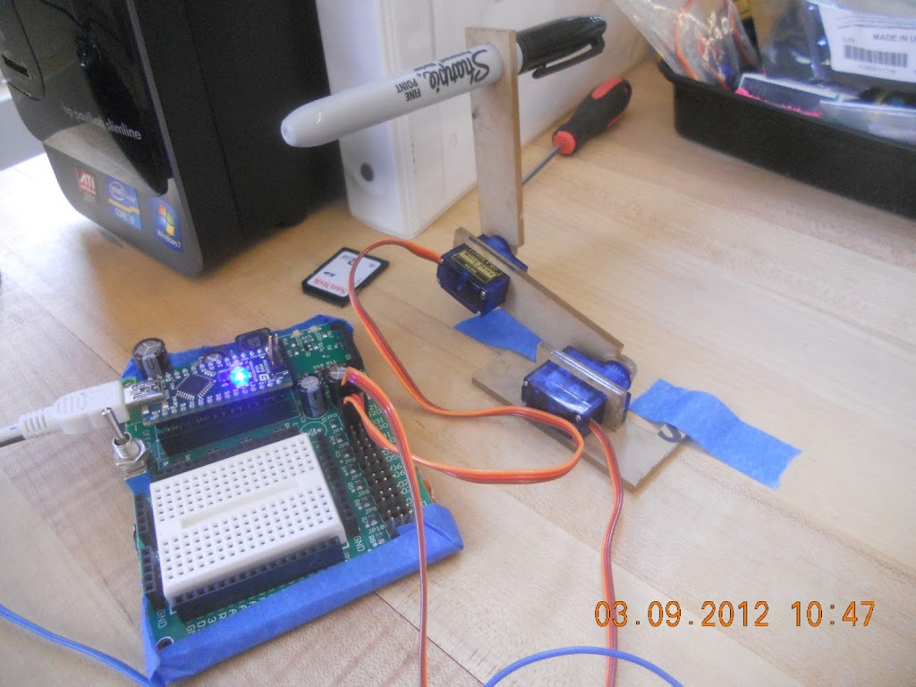
near the end of the designathon

I didn’t even have time to map things correctly, because I thought the presentations began at 5pm but actually they began at 3pm.

The lasercutter files looked like so:

It’s hard to see the cuts. But the pots have flats on their shafts, so the pot arms have semicircular holes that are tightly fit onto the pot shaft to couple rotationally. And for a minimalistic design, the robot arms have servo splines cut into them so they mate directly to the servo.

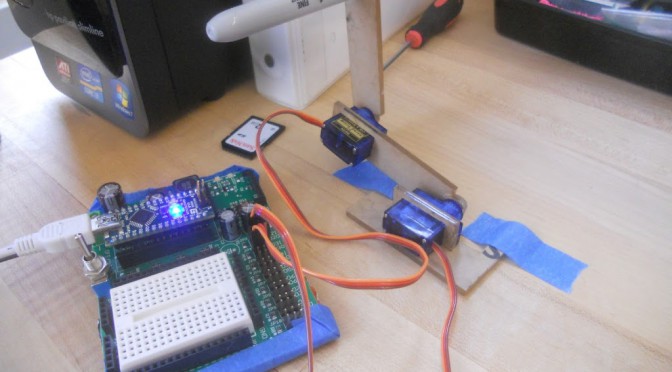
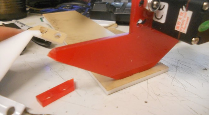
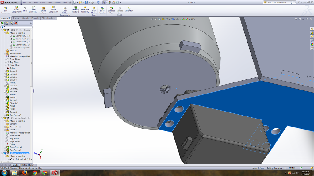
I had the most issues trying to make a press-fit bracket for the servo so that I could couple it to a base. The sides of the servo weren’t particularly flat so the rectangular brackets always broke on installation; I ended up with a C-shaped bracked design.

a frontal image

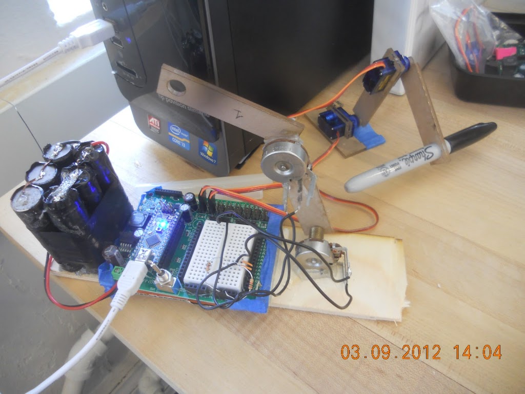
Also, the servos are amazingly torque-ful. I thought the base would be enough to hold it down but I ended up adding tape so that the servo arm wouldn’t swing itself around.

Also to fix, I actually need to build a platform so that the base is heavy enough that the servos don’t push it around and high enough that at zero degrees the width of the servo arm doesn’t cause it to hit the ground.

I also actually did calculations for the servo, or rather used a calculator online, to verify the servos would handle the sharpie weight. Not that I had different servos or anything. (screenshot below)

Oh, another issue I ran into, the servo.write() arduino library uses modulation from 544us to 2400us, while the microservos used 500-2400 us, which gave me this issue where the servos wouldn’t go all the way down to zero degrees when I used myservo.write(0). I took a quick look at “arduino-1.0librariesServo” and found out thatyou can specify these min/max values when you initialize the servo, e.g.

attach(pin ) - Attaches a servo motor to an i/o pin. attach(pin, min, max ) - Attaches to a pin setting min and max values in microseconds 

There was some other funky issue with trying to read a sensor while the servo was drawing power. Turns out I just need more delay in my loop.

Can’t think of anything else for now.

Material Costs

ebay $11.88 
“4x SG90s 9G CYS micro servo motor RC Robot Helicopter Airplane Car Boat + Horns”
so about $3 per servo

The servo specs: http://www.servodatabase.com/servo/towerpro/sg90

Pulse Width: 500-2400 µs sg90

Current Status:
I lost the code, and I broke some of the lasercut pieces, (the usb port for programming the arduino also seems to create a lot of sensor noise and the servo arm kind of did crazy robot arm thing and killed itself) so right now I re-lasercut  pieces and am re-writing the code. Should be up within a week.

===================================

Follows is a live blog of me working on drawbot:

===================================

ebay $11.88 
“4x SG90s 9G CYS micro servo motor RC Robot Helicopter Airplane Car Boat + Horns”
so about $3 per servo
let’s follow this tutorial
confirmation that 9g micro servo can indeed make robot arm: 
okay yay let’s do some math
thanks society of robots

alright, now let’s see some real specs on these micro-servos:

Stall Torque at 4.8 volts = 22.2 oz/in (1.6 kg/cm)

aww… so cute (compare to the 7 to 15 kg/cm ones used in “small” robot arms: http://www.nex-robotics.com/robotic-arm/robotic-arm.html)

So what are the tradeoffs? With a longer robot arm length, I get more range, but then I suffer torque-wise.

Also, need 4 dof — one for the pen to move up and down.

===
7:47pm
some research into simulating robot arms online..
http://wps.aw.com/aw_young_physics_11/0,8076,898588-nav_and_content,00.html

my initial thought was to use processing, but oh hexapods java applets >__<

okay the guy next to me at the hackathon, idk his name, says i should just write it in html5
[edit: it may have been vincent xue]

excellent plan, learn html5

mmm kinematics libraries http://kineticjs.com/

wah html5 games
http://raptjs.com/
okay let’s not get too distracted

hrm kinematics in flash
http://active.tutsplus.com/tutorials/animation/learn-about-linear-kinematics/
===
http://www.societyofrobots.com/robot_arm_tutorial.shtml

frick
i should catch up in 18.06, perhaps
http://commons.bcit.ca/math/examples/robotics/linear_algebra/index.html

==
okay, assume some weights
google: density of acrylic
1.18 g/cm³
thanks google

okay let’s make up some dimensions for a link length
4x16x3 = 192 cm^3 * 1.18 g/cm^3 =
226.56
thanks dot-gridded metric notebook and google

hrm, so about 1/5th of a kg. Wait what? that seems wrong.

oh units -> 0.3cm thick, so = 22.7 grams.

(from actual measurements:
15g for a 3*50*76 mm chunk, or 1.32 g/cm^3

okay now for
pre-built calculator!
😛

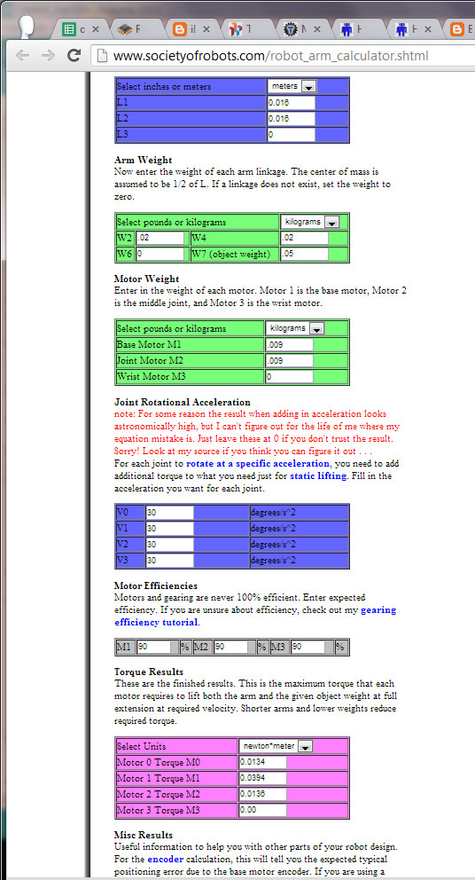
okay not operating near stall torque, that is good

(conversion N m to kg cm is about x10, if you let gravity ~10 m/s/s)
==
8:30
okay, screw this, I am going to CAD some stuff
later: end up not CADing anything
==
3:18
One anime later, and back to staring at robots.
i start watching youtube stanford lectures but am too sleepy
http://www.cs.unc.edu/~jeffi/c-space/robot.xhtml mmm canvas, 2010 2d robot arm simulator

hmm GUI via processing
http://luckylarry.co.uk/arduino-projects/arduino-modifying-a-robot-arm-part-2/

oh! excellent written documentation
http://www.micromegacorp.com/downloads/documentation/AN044-Robotic%20Arm.pdf

===
day 2
haha, still here. i’m so sloowwww at building things, all the other teams are so cool
okay i’m working by myself because i’m weird like that

eww, the servos are doing funky things where servo.write(0) doesn’t seem to go all the way to zero. let’s compare. hitec311 and sg90.
http://www.servodatabase.com/servo/hitec/hs-311

Pulse Width: 500-2400 µs sg90

Pulse Width: 900-2100 µs hitec311

hrmmm.

bam,
arduino-1.0.3librariesServoServo.h

   attach(pin, min, max  ) – Attaches to a pin setting min and max values in microseconds
   default min is 544, max is 2400

==
Adam Libert, DIY waterjet and crazy grad student, drops by and shows me cool robots:
http://medesign.seas.upenn.edu/index.php/Courses/MEAM520

==
serial monitor output:

º’j¤ º’jP ºŠjR ºŠjR º’jT ºŠjR ºŠjR ºŠjT ºŠjR º’jR ºŠjP º’jP º’jT º’jR º’jP º’jR º’jP º’jR º’jR ºŠjR º’jR º’j

Exciting, when I am commanding a servo, it pollutes the analogRead.
Well then.

Oh, I just needed to increase the delay (was using 1). Hmm. I’m not even writing to the servos. I wonder why initializing the servo means the serial loop can’t run fast enough.

==
how the heck does a kit for this not exist already?
http://www.bizoner.com/arduino-6-dof-programmable-clamp-robot-arm-kit-ready-to-use-p-238.html
$250, wow.

==
whee it’s 3 pm and i decided to pitch because I HAVE NO SHAME. 😀 It’s amazing what having the support of a friend can do for you.

screw-propelled vehicle prototype v1 — with soda cans

Yea so I did a CAD thing with a lot of procrastinating along the way.
Concluding thoughts: sleep. Also do more schoolwork / UA work and also apply to jobs. Good plan.
Oh, include more margin of error in general, in this case for the diameter of the can with cat5 cable included (you can see where I bandsawed the top platform just to see how it would do).

  • redo by making platform higher
  • oh and fix the snap fits
  • and make things a bit farther apart

Acrylic, it snaps.

the video is actually made still using this piece. actually maybe the extra degrees of freedom allow the vehicle to actually work.

Stockpile non-flathead style bolts (socket-headsss i want them), I hate using locknuts with non-flathead style ones

Some pictures

those count as bushings right
this is how you’re supposed to couple things to a soda can right
that’s what it looks like in solidworks

more pictures will be added to this album: https://picasaweb.google.com/113942194695013581888/ScrewPropelledVehicle

in which i rediscover the lasercutter: screw-propelled vehicles, making servo horns, and figurine+ruler keychains

i have been making a lot of things lately.
Never enough!
But yes, I rediscovered the lasercutter, and there happens to be one upstairs of MITERS now.*

* [I should really get a Real Laptop (that I can CAD on) and then I have no excuse to hang around upstairs when the MITERS computers are occupied. (or just set up another computer downstairs…) but in the meantime there are excellent computers are the third floor (which as a bonus are tucked away in corners. I have a special affinity for corners).]

My convoluted group loyalty issues aside, last week there was epic snowage, so much that MIT closed down. So then I decided to build a snowbot, or rather a screw-propelled vehicle.
http://en.wikipedia.org/wiki/Screw-propelled_vehicle

Turns out some excellent undergrad wrote a thesis on this topic, with pictures and build and equations!
http://www.wpi.edu/Pubs/E-project/Available/E-project-031411-150953/unrestricted/Ice_Inspection_Robot_MQP,_Final_Report.pdf

So he made his prototype out of PVC pipe. Specifically, giant!diameter!PVC pipe for the augur and 1/4” diameter pipe wound around the large pipe for the threads on the augur. His second revision was tube aluminum with specialty-ordered sheet steel threads (the two were held together with “Loctite E-20NS metal epoxy”. Wow. Heavy-duty epoxy).

Well! I wanted to complete snow-bot in a day so I decided to make it out of coke can + cat 5 cable hotglued onto it (with revision two to be 3d printed).

that is so totally a workable augur. right?

This err didn’t happen. I got distracted by other lasercut projects. But yea, the plan was to attach two continuous rotation servos to turn the coke cans and voila, I would have instant prototype.

note: for the sake of sleep this is going to be an overview post with more detailed / better formatted / all my files–posts to come, but in case I don’t get around to those:

My first step was to discover that I had SpringerRC continuous rotation servos, perfect for the job, but no servo horns. (First of all, note that servo horns are NOT all compatible). Oh noes! Well. Turns out, they are pretty easy to make, despite the total lack of help from this site which just says “lol they are easy to make”:

http://makeprojects.com/Wiki/Servos

A bit of googling and double-checking by counting by hand, I find out futaba-compatible horns have 25 “teeth.” And using calipers I determine the outer and estimate the inner diameter, for which I get roughly 0.02” which order-of-magnitude agrees with the super-accurate measurements made by this dude.

I also, via the internet (and later by trial-and-error) find 3mm acrylic-like plastic to have a kerf of about 0.005”.

So using coreldraw (or inkscape), there is a polygon/star tool, and I enter 25 pointed star. I then eye-ball the “sharpness” parameter, which you have a bit of slack on (the horn teeth just needs to fit between the servo teeth). I also initially set the x-y width to be 0.235”, the exact outer-diameter I measured. When cut out, this servo horn a bit loose but slides onto the servo and turns the servo when it is turned.

yes. my camera has a permanent dust speck somewhere inside it…

Then I iterate. You can see I drew a green and yellow rectangle, for 0.02” + 0.005” kerf, to get the “sharpness” (pointiness of the star) setting right (if you draw it out, to account for kerf, the OD of the star should be smaller by 1/2 kerf and possibly the star’s inner corners should go 1/2 kerf deeper, hence why 16 sharpness with the inner corner somewhere between the length of the green and yellow rectangles. I’m not 100% how sharpness is interconnected with the diameter of the star so it’s hard to say what the exact adjustment should be).

f* yea MS Paint

The laser settings I used for a 120W epilog laser:

Of course, I don’t finish over the weekend and Monday I walk into 2.007 lab (which I am undergrad assisting with, UAing, this term) and there are a gazillion springerRC servos and servo horns. But that’s beside the point.

I also realized that part of my search criteria for LIFE aka a career included “access to lasercutter,” but maybe I am supposed to look for a job that pays well so that I can buy my own lasercutter. Hrm.

Hrm…

Anyway, what else happened? Oh right, Jordan‘s birthday came up. Because she is awesome, I decided I should make her a birthday gift. Inspired by Kat Struckmann’s cruftmas (putz hall secret santa tradition where gift has to be entirely made of cruft, aka free stuff. Oh right, I made a sheet steel bookstand for my secret santa and learned the importance of product design, because the gal I gave it to was like “wtf is this, a shelf?” ^^; #toblogabout) gift to Sterling Harper, aka by the Archer TV show:

image courtesy of jordan.

Oh gosh. I had to use so many programs to make this, I don’t even. No. Anyway, the general idea is to use various selection tools (oh robutts don’t use the polygon tool by itself, it’s so easy to accidentally hit escape and erase all your work with the selection, make sure to use quick-mask model with shift-Q — everything this is orange is not in the selection and everything that is white is) in GIMP on the original image (see: her blog), export selection to path, save path as an SVG, import that into inkscape, use various path tools (difference, something like that) to merge the Person outline with the rectangle outline that I want to cut out to create a stencil-like effect, realize that coreldraw hates inkscape SVGs for whatever reason, save inkscape file as PDF and import and clean up import in coreldraw, still recreate a lot of the work in coreldraw because I am more familiar with sending coreldraw files to the lasercutter, find flowers on openclipart, and then spend a few hours playing around with the DPI / whatever settings because I want to get a raster image of the photograph etched onto the outline. This… doesn’t go so well. Somewhere along the way I decide to add a ruler to the thing, because really, useless keychains may as well have rulers on them. I discover the magical coreldraw “blend” tool, where I can just draw two lines at the beginning and end and then specify how many copies I want to use to blend between them (since the end and beginning lines are the same, all the intermediates are the same as well).

so many rejects. luckily this is all from small bits of scrap other people would probably just throw right out.

Then there were other lasercutter shenanigans, but that’s for another time. Briefly…

Oh gosh that is a topic in and of itself. Inkscape has a gear generator, but then I tried to x-y scale that, so the pitch becomes something strange, and then I import that dxf into solidworks to make a 3d model and also to measure the pitch and other things, and later export it as a dxf from solidworks to coreldraw … … apparently solidworks has a gear generator in its toolbox. I should use that next time.
Oh, food-wise:

Oh also this excellent post on designing sninges, aka how to make acrylic bend:

http://blog.makezine.com/2011/12/08/designing-sninges-in-laser-cut-acrylic/

Guys I should just go do lasercut etsy things. Forget scaling and engineering, and go be a craftsperson >__>;; and sell things at cons or something.
Oh and speaking of bending acrylic, 
Hrm this is rich with possibilities. I CAN EMBED SO MUCH ELECTRONICS IN HERE with this 3d possibility.
Heck I could like embed a mini hexapod in there probably. With a button. So I can hit the button and pop out a small hexapod army from brace/ankle-lets.

HRM. 
Hexapod armies.

*reminds self to talk about microcenter and finding hexy, the kickstarter project funded just seven months ago, on the shelves there….* #toblogabout

Okay, when my blog posts get to the topic of hexapod armies it’s a definite sign that I am procrastinating. Time to get back to CADing snowbot. (CADing a spontaneous robot? wtf? MIT, what have you done to me, that I would prefer to CAD and lasercut something instead of putting things together by hand until it works…)

==
additional resource: list of screws, in case you lose those screws for the horns:
http://www.rcgroups.com/forums/showthread.php?t=914983