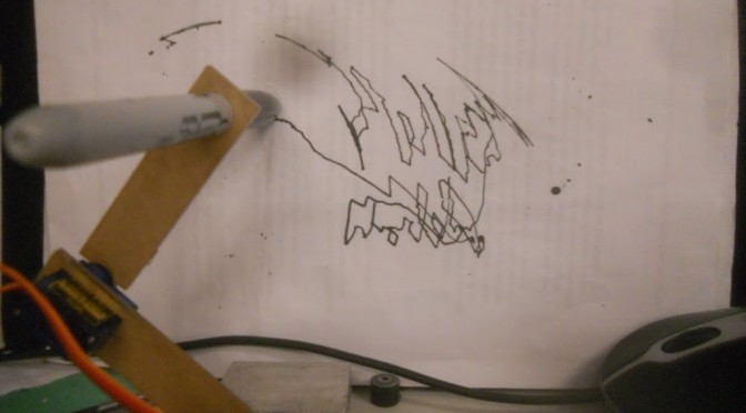
you can see some of the error modes i was encountering in the ^ shaped “straight line” where theta1 was clipping out because I was feeding it negative values based on my inverse kinematics calculated angles
i blame servo jitter for how shaky the lines are 🙂
this took forever and a heaping bowlful of confusion to get to where i am. actually i’m still confused. but basically i spent all day sunday working on this, emailed out to MITERS, and finally a hallmate, pranjal, helped me out (https://github.com/pranjalv123/servoarm) today and fixed where I was stuck at in an hour or two.
essentially he rewrote the code in python (I was actually starting to do this) to graph and understand what was going on. For instance, the bottom-most image is the working envelope of the robot arm;
Isn’t that fascinating? It’s like a yin yang. If you play around with the servo arm this sort of working envelope makes sense.
So turns out my code was decently fine, the negative values just meant I was giving it bad inputs that it physically couldn’t reach given the arm link lengths I’d given it.
We initially tried to wrap the negative values around by doing mod180 ‘ing it, theta1 = ((int)theta1+180)%180 but this gives the sort of trajectory shown in the upper image (I think… it may also be that elbowup needs to be false to generate that sort of trajectory)
setting elbowup to be true fixed a lot of issues to (which makes sense physically as more x,y coordinates can be reached if the elbow is up rather than down, it’s easy to see if you play around with it … see the inverse kinematics chapter on http://www.eng.utah.edu/~cs5310/chapters.html if this elbowup/down stuff is coming out of nowhere — basically there are two combinations of theta 1 and theta 2 that will work for any given x,y coordinate and you just pick whether you want the elbow up or down solution)
and finally the working enveloped helped me pick correct x,y values to feed it. Initially I was just basing my x,y values off of the instructables www.instructables.com/id/Robotic-Arm-with-Servo-Motors/?ALLSTEPS but scaled down 1/3, which was just a guess of mine based on my servo joint limitations versus her motor joint limitations
it is also surprisingly close to the dimensions in mm I give it, eg.
doublehighY=80;// line drawing targets in mm
doublelowY=20;
doublestaticX=20;
will give me a line about 60 mm long (I put the link lengths in as mm), which is exciting.
I’m still not sure what’s going on with why the straight line up and down is at a 45degree angle, but that’s probably a constant offset problem. Fixable either in code or if I set the initial conditions on the angle the links are mounted on the servos better.
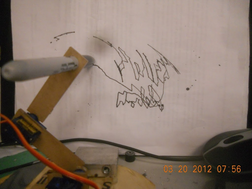
values actually mapped correctly = some semblance of control. mapping painstakingly / experimentally determined
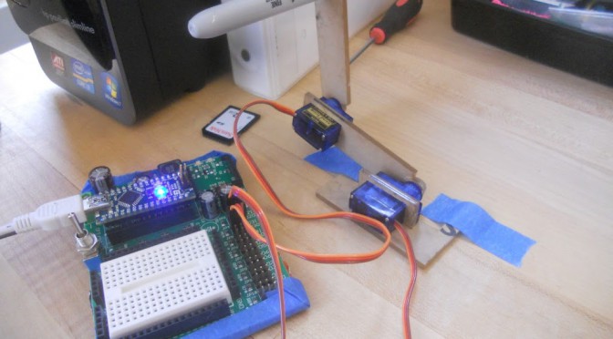
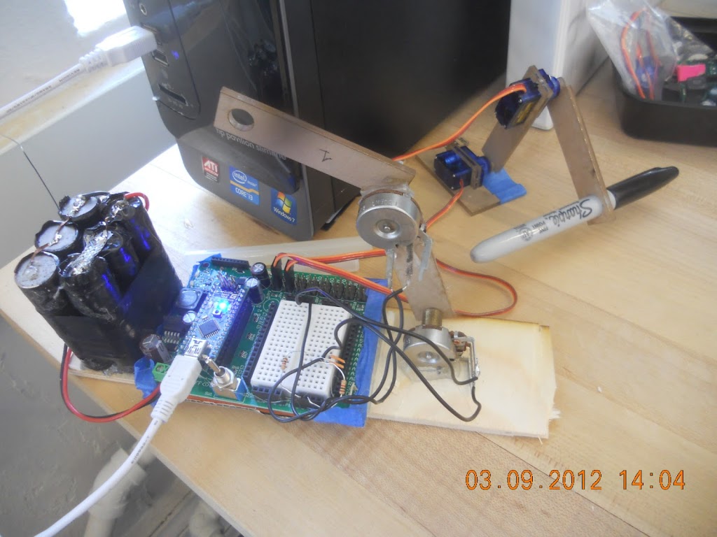
the setup
actually very difficult to write words even with the arm controller (versus twiddling some potentiometers to control the arm), because the potentiometer to servo mapping isn’t precise and there’s a lot of slop (e.g. look at the dead space around the screwdriver)
time elapsed: probably 1 hr including trying to figure out how to draw things and documenting ^^ (~40 minutes to code this and map the values)
/** * @file: RC control of servo * * @description * theta1 = bottom joint pot value, theta2 = top joint pot value * these were experimentally determined, * I had one leg of pot connected to sig5v, the other to a voltage * divider setup with a 1kohm=R2 and being read to A0 or A1 respectively */
There’s a video of it in its final state, with its multitude of issues. *sigh* one day I will actually finish a project. Only the first and last 5 seconds or so are interesting. Cost: ~$6 for the two microservos (!! so cheap), plastic is free, then the board+microcontroller battery is $25+$15+free (probably $10?).
After building hexa-rideablepod, I have definitely been more inclined to daydream about small or fold-able or compact project.
I should update my project todo list.
Anyway, I started at ~8pm on Saturday and finished ~3:30 pm on Sunday (and yes, I did sleep a bit, as well as watch an anime movie (Summer Wars) …
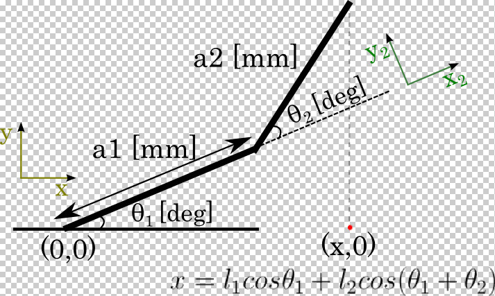
I was a bit confused by the definitions of the variables, since I haven’t done kinematics in a while. In the forward kinematics part it is essentially saying:
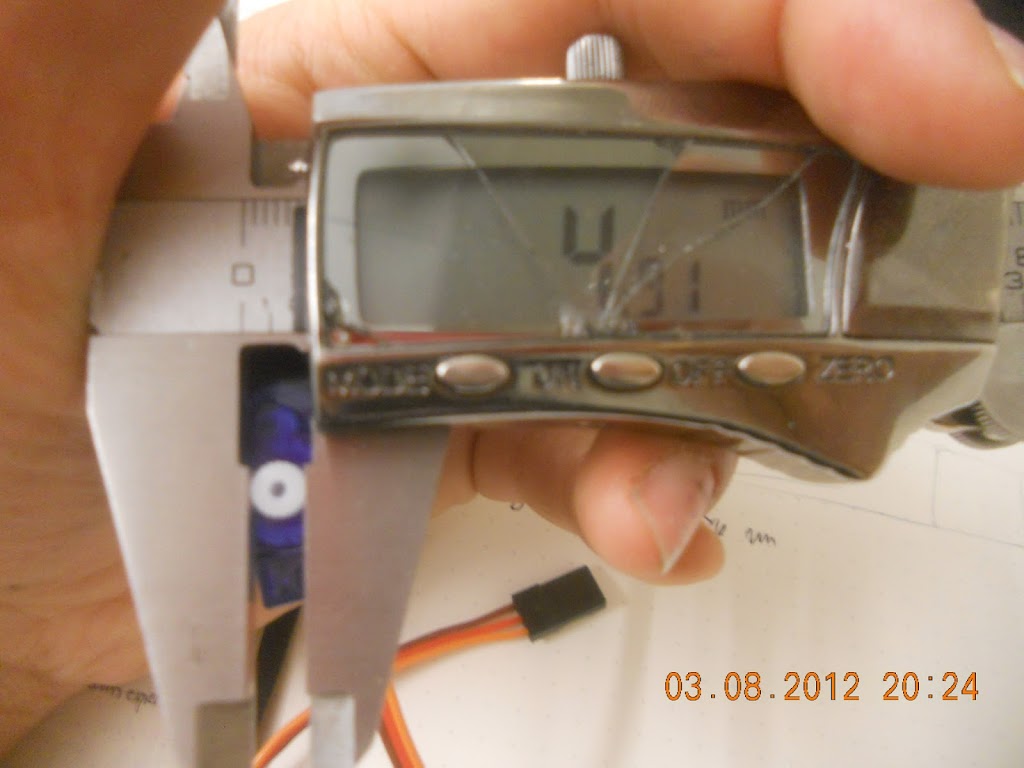
measuring the servo spline outer diameter in order to create lasercut female splines on my parts instead of using the proprietary servo horns. I started around this time. I swear I spent like 30 minutes trying to figure out how many divots it has (21) before just trial-erroring it, lol.
Well, crap. I hesitate — do I want to try to get something done and present a project or not? I eventually decide (and with some support from the awesome Jessica Artiles) that I may as well get more feedback on my ideas. What is there to lose?
Thus, I emergency hot-glued some potentiometers onto pieces of plastic and used that as my control ( a simple mapping of potentiometer values to servo values is all that’s needed) instead of writing IK code. This arm controller design was inspired by http://www.maxjusticz.com/a-miniature-robotic-arm-controller/.
img src my design inspiration, except mine was jankier and used more hot glue
near the end of the designathon
I didn’t even have time to map things correctly, because I thought the presentations began at 5pm but actually they began at 3pm.
The lasercutter files looked like so:
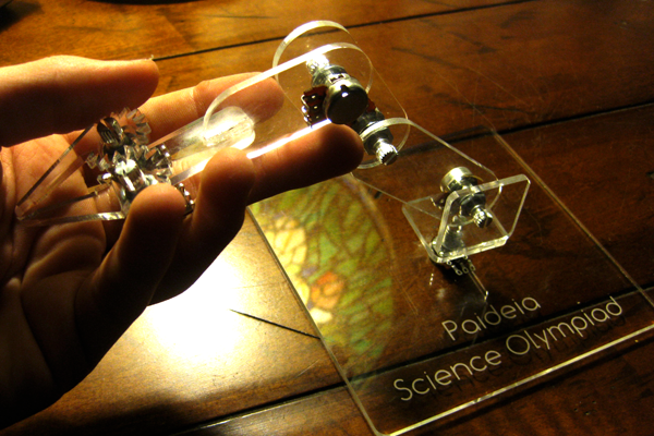
It’s hard to see the cuts. But the pots have flats on their shafts, so the pot arms have semicircular holes that are tightly fit onto the pot shaft to couple rotationally. And for a minimalistic design, the robot arms have servo splines cut into them so they mate directly to the servo.
I had the most issues trying to make a press-fit bracket for the servo so that I could couple it to a base. The sides of the servo weren’t particularly flat so the rectangular brackets always broke on installation; I ended up with a C-shaped bracked design.
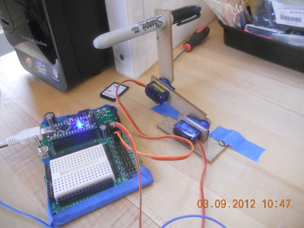
a frontal image
Also, the servos are amazingly torque-ful. I thought the base would be enough to hold it down but I ended up adding tape so that the servo arm wouldn’t swing itself around.
Also to fix, I actually need to build a platform so that the base is heavy enough that the servos don’t push it around and high enough that at zero degrees the width of the servo arm doesn’t cause it to hit the ground.
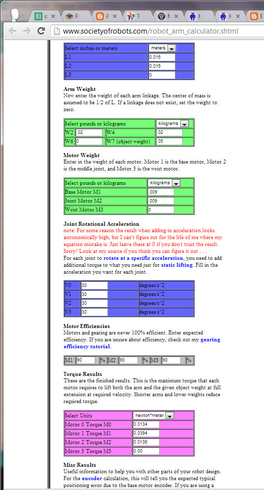
I also actually did calculations for the servo, or rather used a calculator online, to verify the servos would handle the sharpie weight. Not that I had different servos or anything. (screenshot below)
Oh, another issue I ran into, the servo.write() arduino library uses modulation from 544us to 2400us, while the microservos used 500-2400 us, which gave me this issue where the servos wouldn’t go all the way down to zero degrees when I used myservo.write(0). I took a quick look at “arduino-1.0librariesServo” and found out thatyou can specify these min/max values when you initialize the servo, e.g.
attach(pin ) - Attaches a servo motor to an i/o pin. attach(pin, min, max ) - Attaches to a pin setting min and max values in microseconds
There was some other funky issue with trying to read a sensor while the servo was drawing power. Turns out I just need more delay in my loop.
Can’t thinkof anything else for now. Material Costs
ebay $11.88
“4x SG90s 9G CYS micro servo motor RC Robot Helicopter Airplane Car Boat + Horns”
Current Status: I lost the code, and I broke some of the lasercut pieces, (the usb port for programming the arduino also seems to create a lot of sensor noise and the servo arm kind of did crazy robot arm thing and killed itself) so right now I re-lasercut pieces and am re-writing the code. Should be up within a week.
===================================
Follows is a live blog of me working on drawbot:
===================================
ebay $11.88
“4x SG90s 9G CYS micro servo motor RC Robot Helicopter Airplane Car Boat + Horns”
== okay, assume some weights google: density of acrylic 1.18 g/cm³ thanks google
okay let’s make up some dimensions for a link length 4x16x3 = 192 cm^3 * 1.18 g/cm^3 = 226.56 thanks dot-gridded metric notebook and google
hrm, so about 1/5th of a kg. Wait what? that seems wrong.
oh units -> 0.3cm thick, so = 22.7 grams.
(from actual measurements: 15g for a 3*50*76 mm chunk, or 1.32 g/cm^3
okay now for pre-built calculator! 😛
okay not operating near stall torque, that is good
(conversion N m to kg cm is about x10, if you let gravity ~10 m/s/s) == 8:30 okay, screw this, I am going to CAD some stuff later: end up not CADing anything == 3:18 One anime later, and back to staring at robots. i start watching youtube stanford lectures but am too sleepy http://www.cs.unc.edu/~jeffi/c-space/robot.xhtml mmm canvas, 2010 2d robot arm simulator
Exciting, when I am commanding a servo, it pollutes the analogRead. Well then.
Oh, I just needed to increase the delay (was using 1). Hmm. I’m not even writing to the servos. I wonder why initializing the servo means the serial loop can’t run fast enough.


