Tag Archives: pov

RGB LED Graduation Cap Shenanigans, MIT Graduation Report

I present here my derpy graduation cap, based off of http://learn.adafruit.com/rgb-led-strips/overview:

thanks Jamison (http://thevariableconstant.blogspot.com/) for the picture!

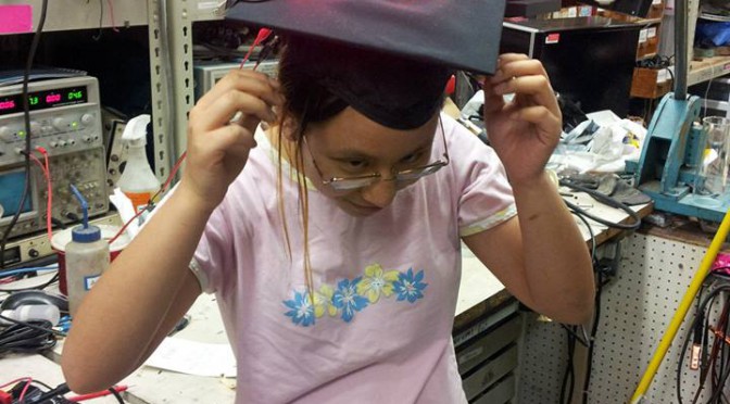
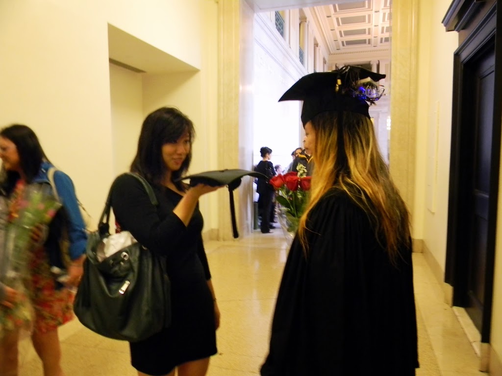
Here it is, just finished at MITERS and still tethered to a power supply. Later I electrical taped on a lipo battery,  I kid you not.

From the front it looks normal, which is unfortunate for the graduation video, but whatever, I tried.

Only if you get some height above me can you see the lights.

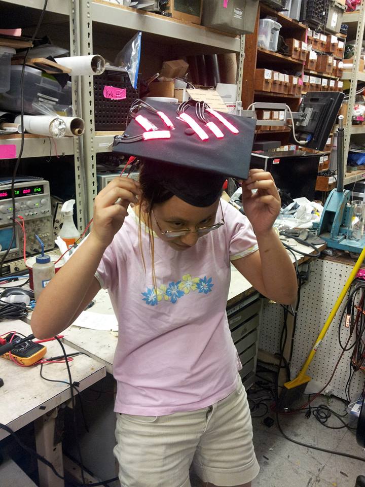
what it looks like from the side. yea I can’t believe it got through security too, especially after Jordan‘s kawaiicopter cap that she worked on all winter break was rejected :'(

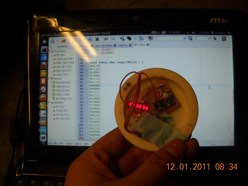
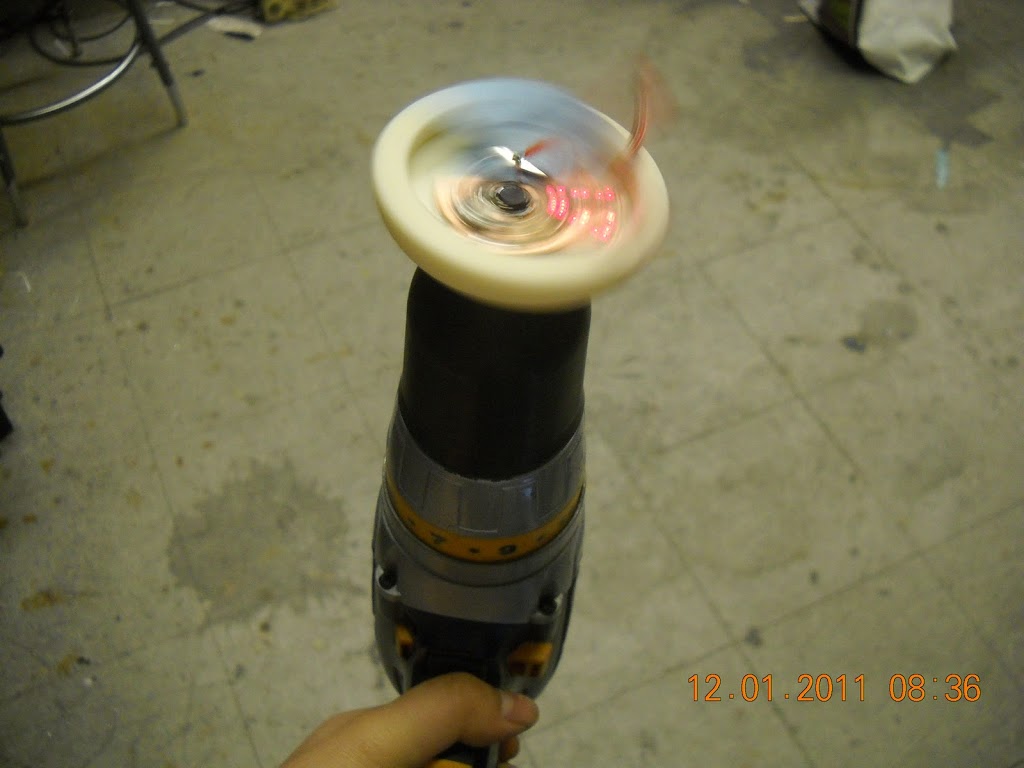
The original plan was to have a spinning RGB POV display, ala the plenitude of persistence of vision clock displays out there.

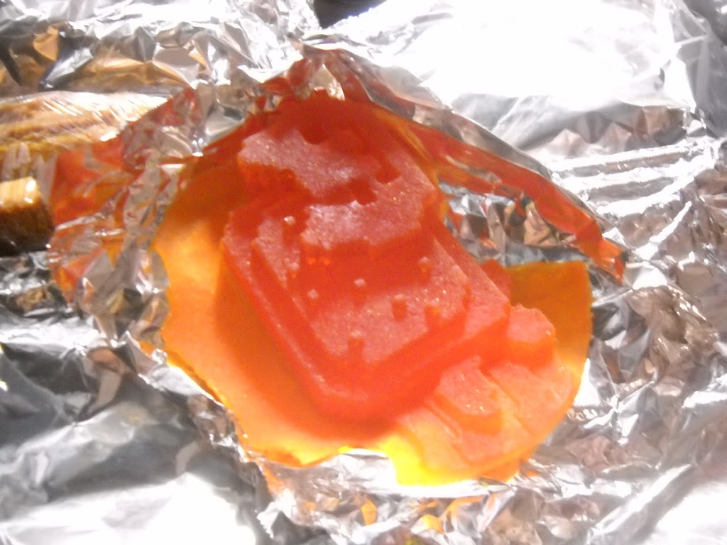
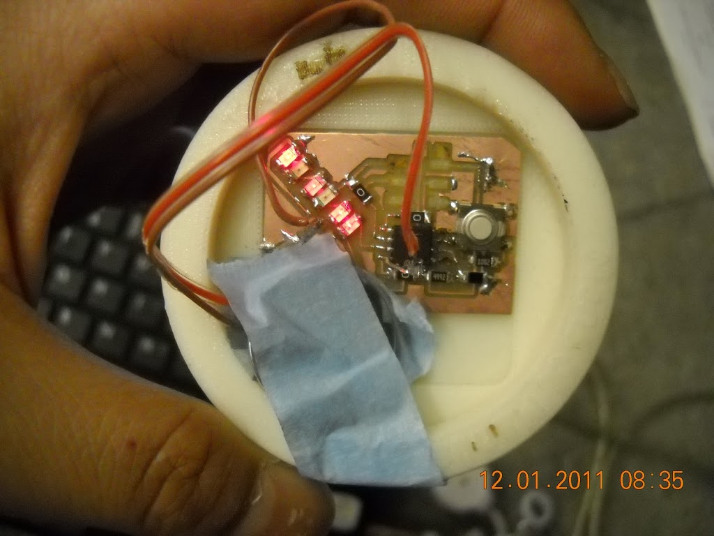
I even milled out a board for it, based on the fabduino files.

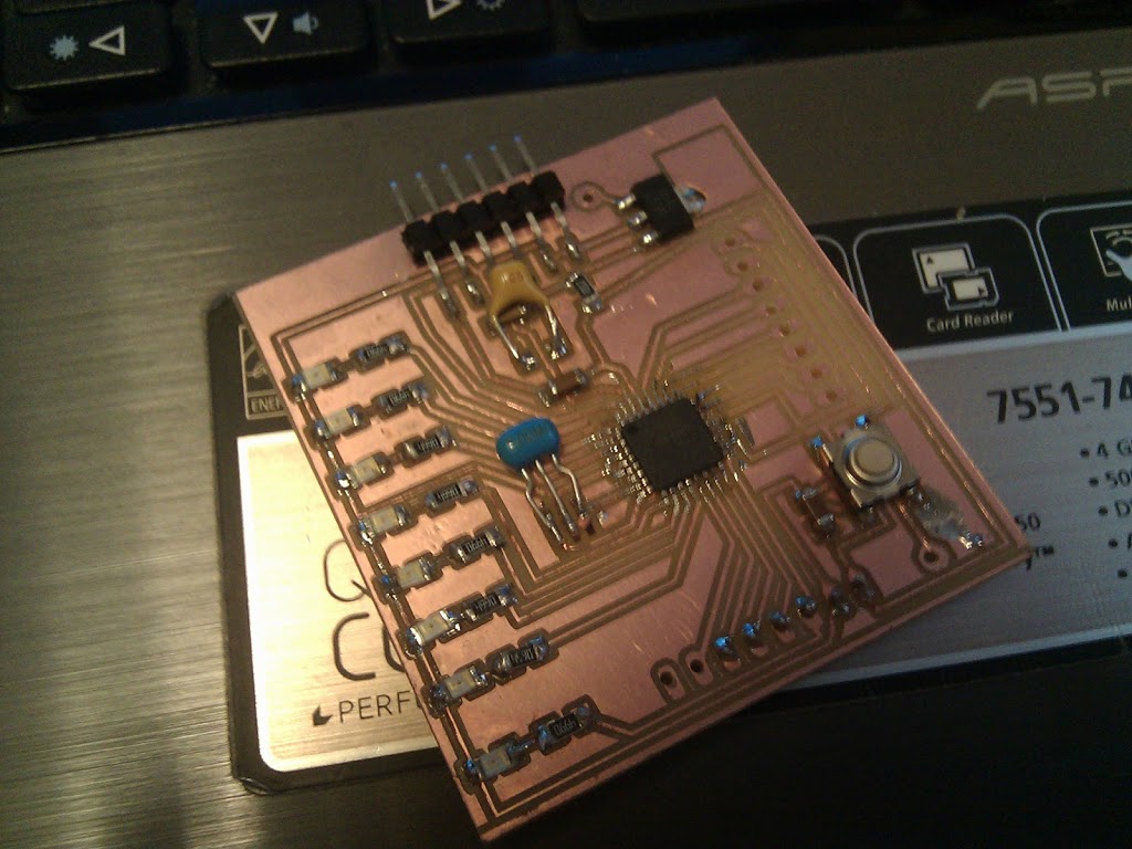
cute non-RGB 7 LED pov board

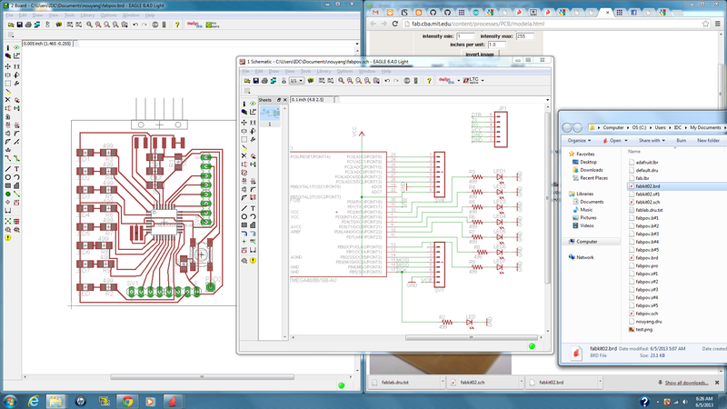
I can upload the eagle files if anyone wants, but since I haven’t gotten it to work and I can’t be sure there’s nothing wrong with the circuit I don’t want to put the effort into putting it up. This was my first exploration of the autoroute tool, which seemed to work pretty well.

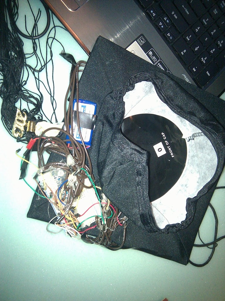
Anyway after pulling two almost-all-nighters working on that project, I gave up when I couldn’t get the arduino bootloader burned onto the atmega (couldn’t get it to program at all, actually — hit a Target not found error). The cap I actually ended wearing was very simple to make and took about 6 hours total, including time spent trying to waterproof it with hot glue and saran wrap. (Most of the letters are stuck on there with the original backing tape that came on the strip). I didn’t have black wires so I used thick brown but still single core wire. I also probably should have done a 6 LED strip for the “I” and just covered up the center portion with electrical tape. Instead, I just skipped the dot on top of the “i”.

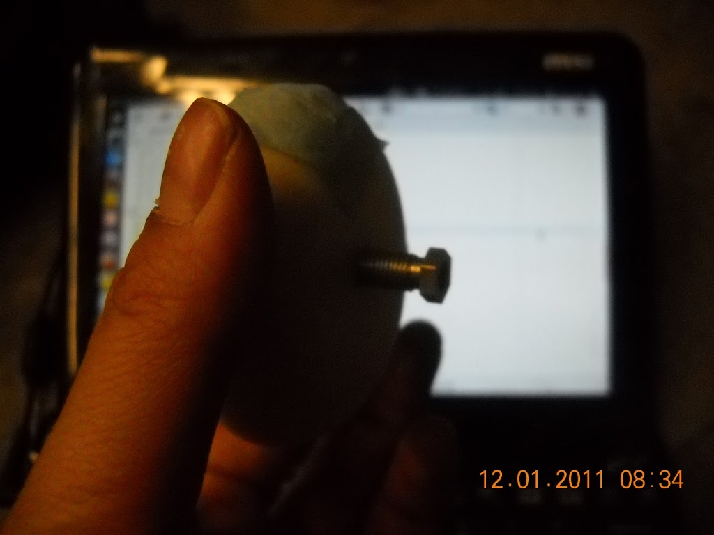
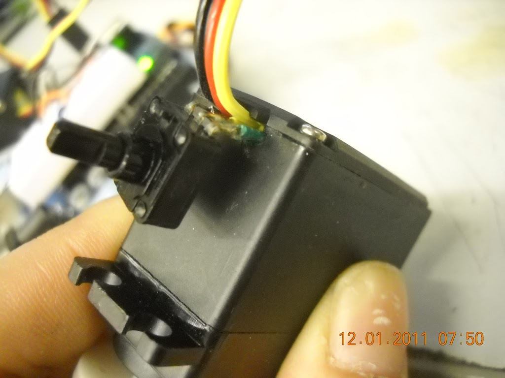
I also found this tool supppeerr useful, way more useful than the helping hands, for holding thick and relatively unyielding wires together so that I could solder them:

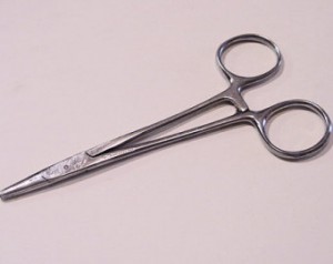
src: http://www.orangenarwhals.com/wp-content/uploads/2013/06/il_340x270.329862126-300×238.jpg
http://www.etsy.com/market/surgeon_tools?ref=listing_tag

If you look carefully there are also two burn marks on my cap. I just colored the cardboard underneath with sharpie.

I also would have taken off my cap and showed it to the camera as I was coming down the ramp after getting my diploma if I knew how graduation worked.

I should have sanded down all the wires because I think a lot of the joints were cold solder joints (this bit me when I was repositioning the letters), but it worked okay and is probably the most robust of all the projects I’ve done so far because the circuit is encased in hot glue. Sorry arduino mini! (I potted that into the breadboard). The circuit itself is super straightforward, 3 FETs directly driven by the arduino. See http://learn.adafruit.com/rgb-led-strips/overview.

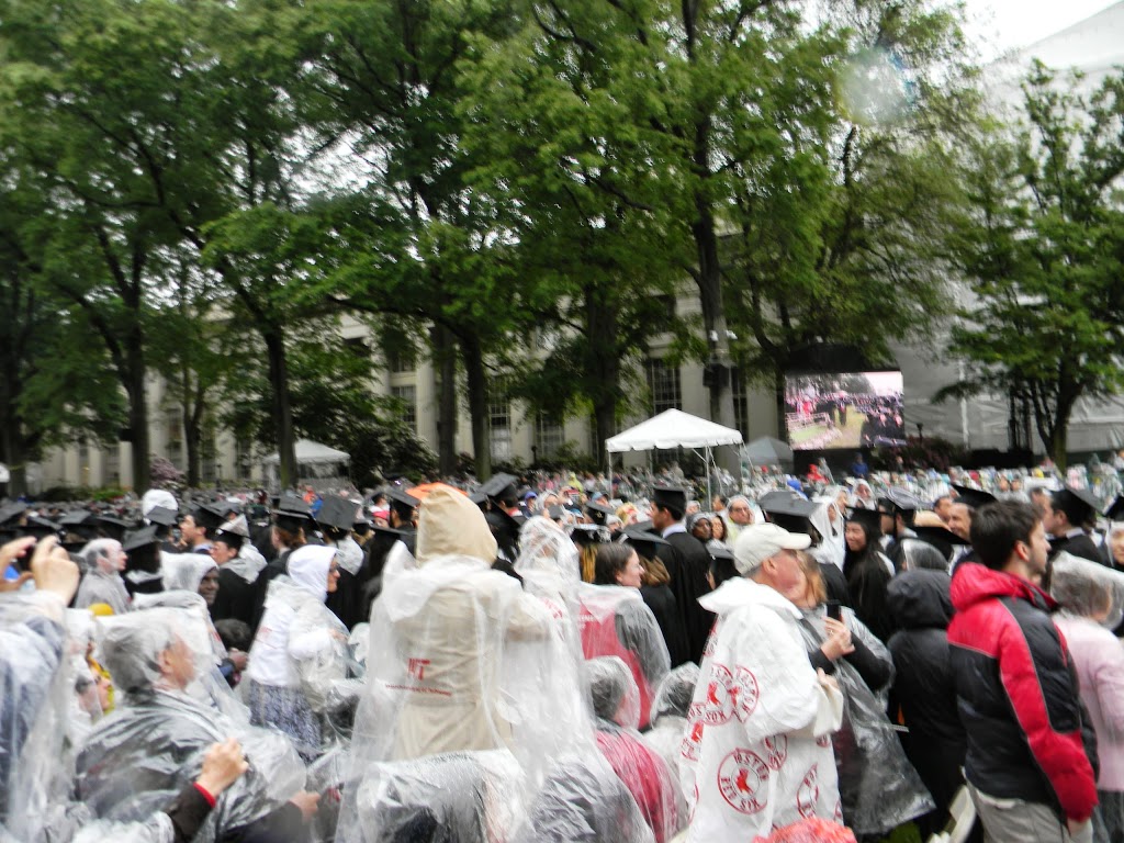
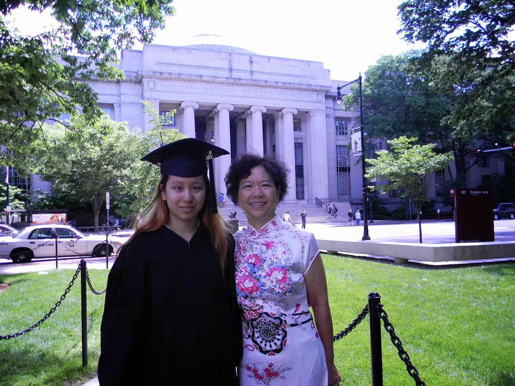
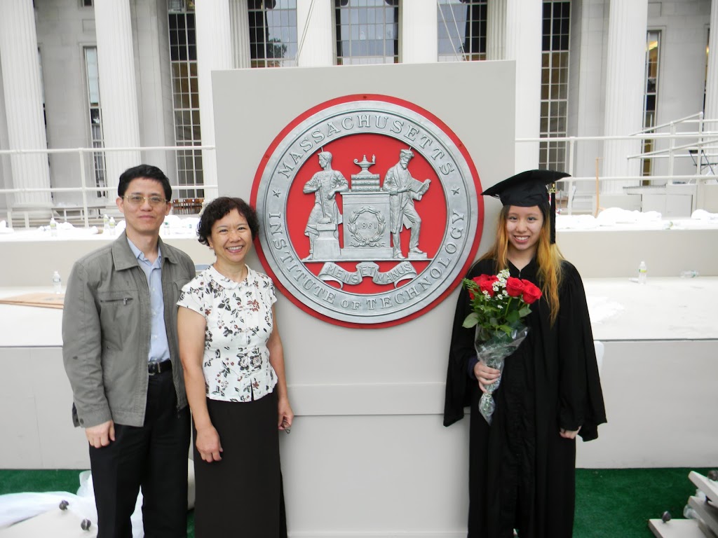
This is what graduation looked like for the parents.

Graduation itself was simply wet and miserable. I was on-and-off shivering by midway through and the list of names seemed endless. I’m sure they were rushing toward the end.

========================
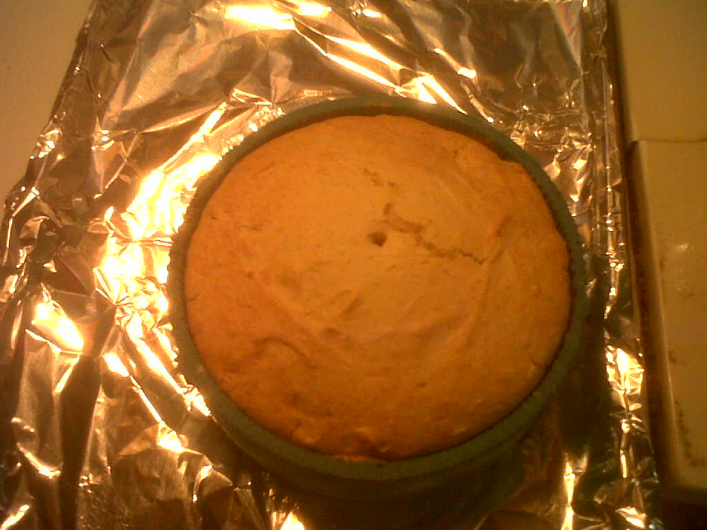
APPENDIX: Milling circut boards on a Roland modela mill (in the IDC)
========================

Ultimate lesson learned: Make your traces at least 16 mil, 12 mil does not work!


https://github.com/radikaldesig/Arduino-POV-minimalist/blob/master/Arduino%20code/fonts.h
It’s a 5 LED font.

The fabduino I will be running (a waste to use it for just 7 LEDs, but I don’t have the time to deal with not just reusing other people’s POV code)
How to use the roland modela mill
Eagle libraries
modela@ubuntu:~/Documents/nouyang$ sh eagle-lin-6.4.0.run 
1/tmp/eagle-setup.4298/eagle-6.4.0/bin/eagle: error while loading shared libraries: libssl.so.1.0.0: cannot open shared object file: No such file or directory
ugh, let’s try troubleshooting this
sudo apt-get install libssl-dev
modela@ubuntu:~/Documents/nouyang$ lscpu
Architecture:          x86_64
CPU op-mode(s):        32-bit, 64-bit
Uhmm… okay nope. Switching back to a windows computer. A shame. : / I really ought to switch over to something more happy running on ubuntu someday.

Pin mapping
http://arduino.cc/en/Hacking/PinMapping168

FTDI headers:
DTR,

How to create board outline in eagle:
http://www.electro-tech-online.com/general-electronics-chat/31558-problem-cad-eagle-how-draw-board-space.html

Eagle MAS.863 documentation

http://fab.cba.mit.edu/classes/MIT/863.09/people/hannah/modela.html

Design rules:
http://academy.cba.mit.edu/2012/labs/providence/tutorials/07.html
http://fab.cba.mit.edu/content/processes/PCB/
http://academy.cba.mit.edu/classes/electronics_design/index.html

5V 1A regulator is in a SOT-223 package
Fab lab inventory
http://fab.cba.mit.edu/about/fab/inv.html
LM2940IMP-5.0CT-ND
http://octopart.com/datasheet/lm2940imp-5.0%2Fnopb-national+semiconductor-1009434-134675
input gnd output

hmm tangent about IC naming (78xx = vreg)
http://blog.screamingcircuits.com/2013/01/more-cautionary-tails.html

Hmmm eagle files for this vreg
https://www.sparkfun.com/products/595
gnd out in, so pin assignments are wrong, should be easy fix
https://github.com/sparkfun/SparkFun-Eagle-Libraries
https://github.com/sparkfun/SparkFun-Eagle-Libraries/blob/master/SparkFun-PowerIC.lbr
MAke sure to download zip file! OTherwise file does not download properly (adds some html comments at the beginning)
Currently the Vreg-LM1117 package is
1 ADJ
3 IN
2 OUT
4 OUT@1
which matches the datasheet https://www.sparkfun.com/datasheets/Components/FAN1117A.pdf 1:GND, 2:OUT, 3:IN.

However for the LM2940 I want
1:IN 2:GND 3:OUT

Steps ish (very incomplete)
Library>Open>Sparkfun-PowerIC
LIbrary>Device>LM1117
Connect> Disconnect all of them
Create new device

Grid dimensions in autorouting:
https://forum.sparkfun.com/viewtopic.php?p=76309

Export dpi?
http://academy.cba.mit.edu/2012/labs/providence/tutorials/07.html

then export as a png (file — export — image)
settings should be MONOCHROME and 500 DPI – this will export a image with white traces.
Make sure the color mode is set to greyscale: image > mode > greyscale
then export Dimenson layer for milling the outside of the board
Remember: the Modela cuts out the DARK and leaves white!

Correction! It should be both the top and pads layer.

http://academy.cba.mit.edu/2012/labs/providence/tutorials/install_fab_modules.html
just type in
~$ fab

… upon trying to make path:
      distance 0.800000, 140873 exterior points remain
Segmentation fault (core dumped)

must run as sudo
~$ sudo fab


Nyancat cake mold, working PoV [not so yoyo], vending corkscrew test (mod servo for continuous rotation)

nyancake
Uhh I’ve been doing a lot of blogging and neglecting my other work, so here is minimalist style ftw.

nyancake? nyangummi?

My hall’s thanksgiving (putzgiving, alums come back for this) was two Saturdays ago. I tested out the nyancat cake mold:

for ease of “parameter optimization” runs, I used even-simpler-cake-recipe: cake mix and sprite as the only ingredients (apparently a dieting trick. comes out fine, although for molds probably want to let bubbles settle for a bit after pouring and before intensive mixing).
apply release agent, aka cooking spray / pam — otherwise doesn’t come out well. also,  sprite+cakemix mixture should not be too gloopy. add flour if accidentally pour too much sprite.

many fail results. Here, did not let bake long enough. (much longer than box says — I baked a bit lower temp based on silicone mold research, ~325deg C, and for say 1 or 2 hours)
demolded too quickly, also did not cover in saran wrap to retain moisture afterward
nyancake party~! nyan nyan nyan
probably the best of all my nyancakes. you can see that the minimum mold feature size — the sprinkles — were too small for the resolution of the cake mix and actually resulted in holes.
speed cooling jello in freezer. recipe used: the lego gummies from instructables
nyanjello = almost perfect mold replica. you can see the sprinkles are supposed to stand out, as opposed to how the nyancakes turned out. however, more limited / difficult coloring opportunities with jello than with cake (which you can just apply frosting / food coloring to)
Persistence of Vision Yoyo
I also figured out the issue with the MAS.863 makefiles causing my weird “compiler” bug (actually, compiler options / makefile bug):

Class-based makefile includes:
avr-objcopy -j .text -O ihex ./v0.1.45.out ./v0.1.45.c.hex
man avr-objcopy
       -j sectionname
       –only-section=sectionname
  Copy only the named section from the input file to the output file.
  This option may  be  given more than once.  Note that using this
  option inappropriately may make the output file unusable. >__> <__<
So the class makefiles should be fixed to include “-j .data”The internet says
“The makefile above DOES NOT create a proper HEX image and is a bad example. When creating an  image, not only does the text section (which holds the code) need to be included but the data section (which holds any initialized data) also needs to be included.
The remedy for this is correct .hex rule to to copy the data setion as well
Example:
$(OBJCOPY) -j .text -j .data -O ihex $(PROJECT).out $(PROJECT).hex
http://www.micahcarrick.com/avr-tutorial-digital-output.html

bmayton: that actually explains a lot of odd bugs that I’ve been seeing with people

using constant arrays, since the array data is never getting copied into the
program

So the actual model of what was causing my bug was, I believe, without calling another function the compiler goes ahead and uses the array to insert the correct commands into the compiled code. But when I used a subfunction, the compiler loads the subfunction which the microcontroller calls, but the ucontroller does not have the array data to look up what to set DDRB and PORTB to.

Anyway, then I proceeded to hack together terrible!code and get PoV working. I used oloepede’s sample image ‘cos I’m all about the laziest and quickest tests and ‘cos olopede is awesome.

eheh derp ripped off ISP traces / headers
works fine waving it by hand (without camera extended exposure time, hard to see entire “olopede” message — can see maybe three letters at a time. dead reckoning PoV timing — no sensors.) 

Doesn’t do so hot on the drill. Mess with timing? Although I spun it slow and fast (and in-use yoyo spins quite fast). May require sensors (fan pov as seen on dealextreme — product designer has better idea of speed of motor while yoyo has more variable speed. maybe they used hall effect sensors, ‘cos it was resilient to me slowing down the blades.) to get stable image.

See video:
https://picasaweb.google.com/113942194695013581888/PoVYoyoPersistenceOfVision#5681157457783660930

Vending machine
Right, essentially two weeks until final projects due. Aka time to start cramming on vending machine.

What do I have on hand? Arduino uno, extra servos leftover from when I bought out all the old 2.007 servos., zipties, handheld drill, a corkscrew. Found some rectangular metal thing to act as guiderails lying around MITERS scrap pile. Also found a block of wood lying around the floor.

Mod a servo  to be
continuous rotation servo
(essentially turn it into a cheap RC motor that comes with motor speed controller in a convenient package for mounting) —
aka remove mechanical stop on gear 

apply flush cutters to stop on gear

and remove pot, which like all pots doesn’t turn infinitely — make sure to be gentle ‘cos pot is held in by internal screw, why it doesn’t just fall out normally

see blurry screw at bottom. Also, I wasn’t gentle and cracked the PCB. Maybe it is inevitable for these servos (motor is soldered onto pcb so not much flexibility there) to get to pot screw. Surprisingly the servo still works…
stick pot on outside, chew a hole for it in the casing — i abused flush cutters

see How to Hack a Servo by Daniela Faas http://stellar.mit.edu/S/course/2/sp11/2.007/courseMaterial/topics/topic12/other/Servo_Hack_large/Servo_Hack_large.pdf)

springs / coils
Attach to corkscrew (from real vending machine) I bought off of ebay to see what real mass manufactured ones are like so I can make fake ones DIY like http://www.instructables.com/id/Make-your-own-springs-in-seconds/

Drill out servo horns (1/8” bit fits zipties I found) and attach to corkscrew with zipties

it vends a block! haha. terrible setup is terrible.

Video here:
https://picasaweb.google.com/113942194695013581888/VendingMachineOpenHardware#5681154916854562050

Yea, not a very interesting proof-of-concept (a “duh are you an idiot” one), but it was very satisfying to me.

Oh right, I tried to use hot glue to hold the pot in one place, since that affects how the servo reacts to servo.write() (pot adjusts when it goes fwd/reverse) — I just used
myServo.write(50) with a 0.5 sec delay
myServo.write(90) with a 3 sec delay
myServo.write(130) with a 0.5 sec delay
to calibrate the pot so that servo was completely still at 90. And then attempted to hot glue. a bit flaky– not good enough for long-term banging around but good enough for dirty proto.

yes, i stole arduino from hexarideablepod. arduino uno with a small breadboard on top and 3 male header pins to connect arduino (Vcc, Gnd, and SIG — arbitrarily pin 2 in my case) and servo. unplugged in this pic.

Not clear from pics, but to test it I’m holding the servo still with my hand.